10% Off Sitewide Sale + Free Shipping No Minimum*
Intermatic Pool Timer Troubleshooting
The most common pool timer used for inground pool pumps is the Intermatic time clock. These clocks determine when your pool pump turns on, and how long it runs. Intermatic time clocks are the workhorse of your pool equipment collection, and oftentimes outlive the equipment they control. But eventually, like all equipment, intermatic clocks wear out and need to be replaced or repaired.
In this post, we discuss a few quick and easy ways to troubleshoot your pump's Intermatic timer clock problems. No matter what caused the issue, there is typically an easy fix!
Incorrect Time Due to Power Loss
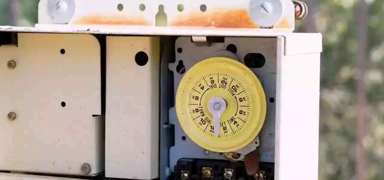
To reset the time clock to the correct time, grasp the outer edges of the large yellow dial, and pull gently outward. This will disengage the dial and allow you to spin it in either direction. Set the current time to the center time pointer, pointing downward at 6 o'clock.
Intermatic Time Clock Not Moving
Look into the visual motor check window, near the top of the timer mechanism. If power is coming to the timer motor, you will clearly see the gears moving through the small window. Then turn the breaker, that the time clock is connected to, off and back on again. If there is still no movement, test the wires coming into the time clock to see if power is reaching the time clock. Remove the plastic insulator cover, and use an AC test meter to check for power on the terminals where the wires from the breaker connect to the time clock.
If power is reaching the clock, but the motor gears are not turning, that usually means either something is jammed in the gears, or the timer motor has burned out. It could also be loose wires, either on the time clock terminal board, or on the timer motor. With the breakers turned off, remove the mechanism from the box. Use a power meter set on AC volts to verify the power is off, before handling the timer mechanism.
If power is reaching the clock, and the gears are turning, but the dial is not turning - this means the gear on the back of the dial is not engaged. Pull the timer out and turn it to the correct time. As you release the dial, you will feel the gears engage.
Dead Intermatic Timer Clock Mechanism
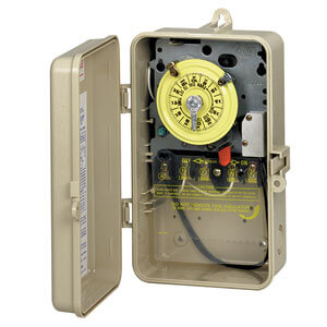
If the motor or wires are faulty in your Intermatic time clock, it's time to replace the mechanism. Turn the power off at the breaker box and carefully remove the wires to the clock. Then remove the mechanism by pressing the clip at the top of the timer box. Pop-in a new timer mechanism, and replace the wires to the previous configuration.
Intermatic time clock motors can be replaced, but unless the time clock is brand new, it's best to replace the entire Intermatic mechanism.
Loose Pointer or Timer Dogs
The screw in the center point timer occasionally comes loose due to vibrations from the pump and filter. Simply screw it back into place until it's snug. Same goes for slipping timer dogs! Gently tighten the screws to securely hold the dogs in place.
Manual Lever is Hard to Flip
Spray WD-40 or any kind of lubricant onto the manual lever to loosen it. If it doesn't improve, inspect the contacts behind the time clock for insect infestation.
How to Wire an Intermatic Pool Timer
First, verify the power is turned off at the breaker panel. For extra safety, shut-off the 'Pool' breaker on the main home panel too. Below is a breakdown of how to wire different Intermatic timer models.
240V or the T104 model
The 240V or the T104 models have 5 brass screws (terminals) underneath the plastic insulator cover. Refer to the wiring diagram on the timer door for more information.
After securing the wire conduit (flexible or rigid) to the box, knock out with the proper 3/4" conduit connector. First, secure the green ground wire to the green ground screw, then connect the other two wires to terminals #1 and #3.
120V or the T101 model
The 120V or the T101 model has 3 brass screws (terminals) underneath the plastic insulator cover. Check out the wiring diagram that comes with a new timer, or is printed on the door of the timer box.
Secure wire conduit to the knock out with the proper conduit connectors, and first connect the green ground wire to the green ground screw labeled GRD. If your 120V wires are properly colored, the White wire connects to terminal A, and the Black wire connects to terminal 1. If unsure, the White (Neutral) wire connects to the neutral buss bar in the breaker panel, and the Black (Line) wire would connect to the circuit breaker.
Tighten down all brass screws securely, to hold all wires firmly in place. Replace the plastic insulator cover, turn on the power, and observe the visual motor check.
And there you have it, the quick and easy ways to troubleshoot common Intermatic pool timer problems. For any wiring concerns, always refer to the wiring diagram printed on the inside of the timer door. Check out our online selection of new Intermatic timer clocks at InTheSwim.com!